Calibrate cameras
![]() Supported for: Instance segmentation – Picking and grading
Supported for: Instance segmentation – Picking and grading
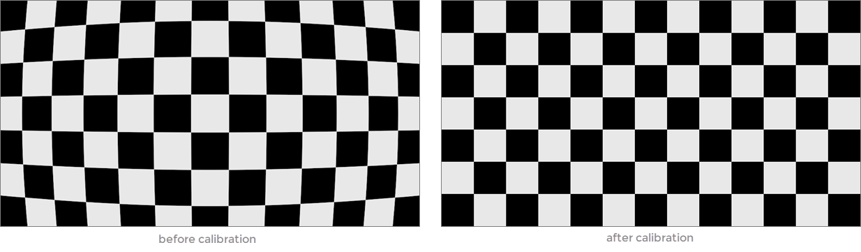
Camera calibration is essential for accurate geometric measurements in industrial quality control and robotics. Capturing images of a known calibration target maps image pixels to real-world geometry.
This method applies to 2D scene measurements where detections occur on a plane perpendicular to the camera’s viewpoint. The calibration target consists of a printed grid of tags. A suitable layout for your application will be provided by Robovision.
Calibration plate requirements
- The calibration target is an evenly spaced grid of tags from the same Apriltag family, all of identical size.
- Each tag includes a 1px white border, which is included in the tag's overall size.
- Tags are arranged in ascending order based on their tag IDs, starting from the upper-left corner and proceeding row by row to the lower-right corner.
- The calibration target must be placed flat on the conveyor belt in view of the camera.
- The center of the tag with ID 0 serves as the world coordinate (0,0,0). The x-axis aligns with the grid columns, while the y-axis aligns with the grid rows.
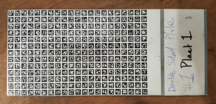
The following image features a calibration plate with a black background.
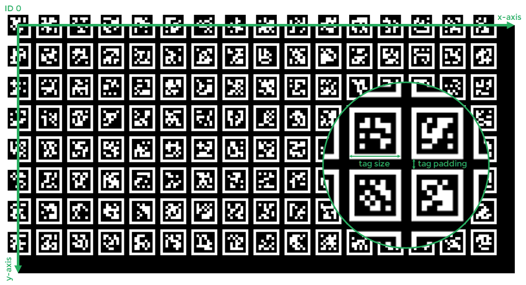
Image capture methods
During calibration, at least one image must be captured. This can be done by configuring the camera for either physical triggering or interval-based capturing:
- Hardware triggering: Configure the camera to receive a hardware trigger signal and send the signal during calibration (for example, by pressing the dedicated button).
- Interval-based capturing: Configure the camera to capture images continuously at a specified interval.
Calibration best practices
- To maintain tag alignment during image capture, use a rigid calibration plate.
- Measure the tag size after printing the calibration plate to verify accuracy.
- To ensure comprehensive calibration, cover the entire conveyor visible to the camera with tags.
- Since calibration plates are more reflective than the conveyor, you may need to reduce exposure or adjust other camera settings.
To calibrate a camera configuration
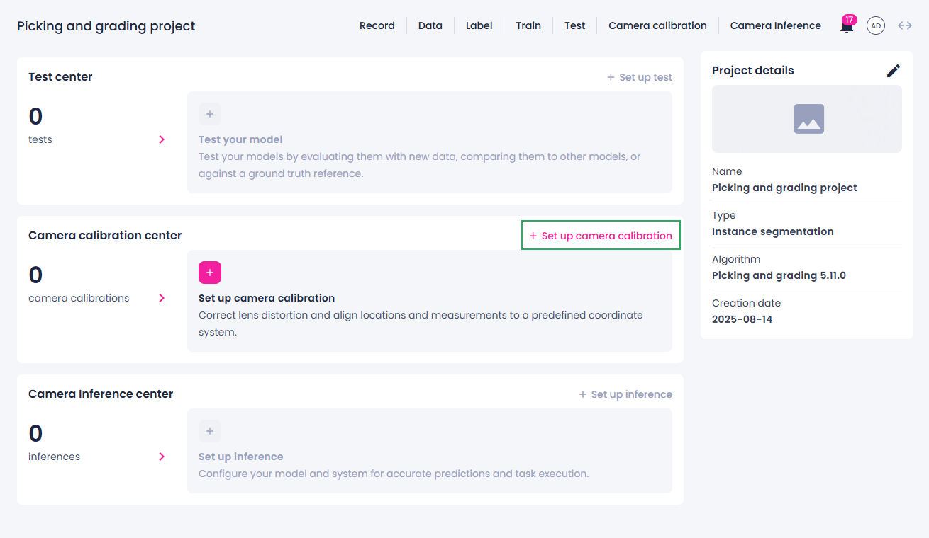
- In the Projects module, click the necessary project.
-
In the Camera calibration center section, click Set up camera calibration.
-
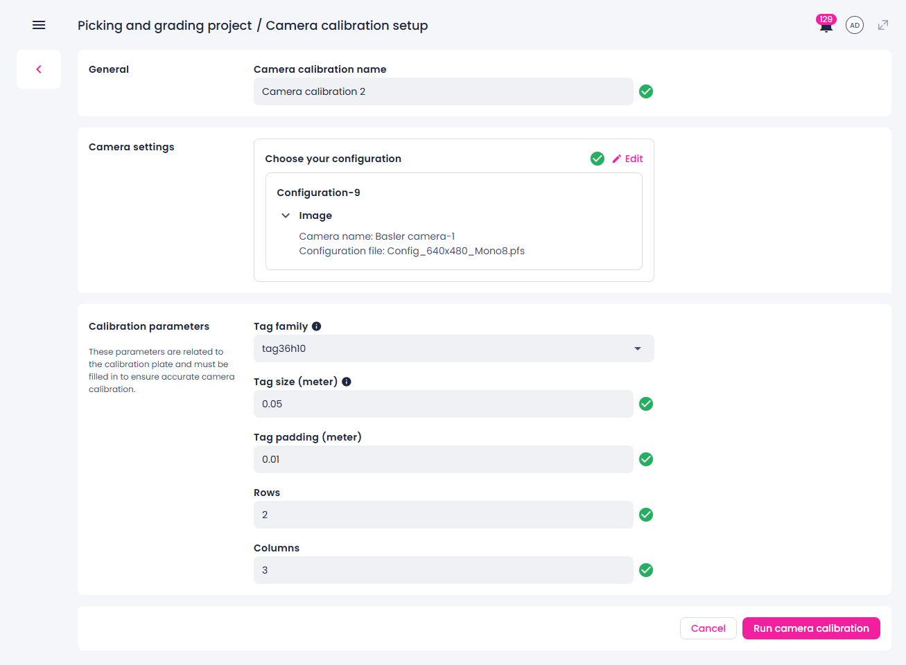
If necessary, edit the default calibration name.
-
Select a camera configuration and check its configuration file.
If the configuration file isn't suitable for calibration, edit the camera configuration and upload the correct file before proceeding.
-
Enter the calibration plate parameters:
- Tag family – type of pattern on the calibration plate.
- Tag size – physical size of each square tag (its width or height).
- Tag padding – spacing between the tags.
- Number of rows of tags in the calibration pattern.
- Number of columns of tags in the calibration pattern.
-
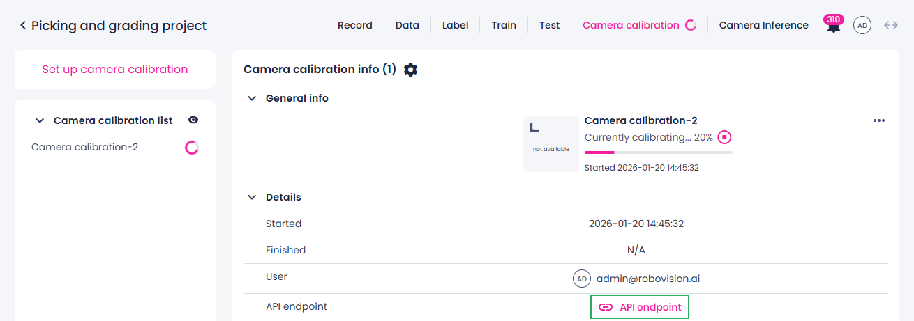
Start the calibration by clicking Run camera calibration.
You are redirected to the calibration center where you can monitor the calibration process and view its outputs. You can control the visibility of calibrations in the Camera calibration center section using the eye icon.
-
Depending on the camera configuration, do one of the following:
- Trigger the camera using a hardware signal to capture at least one image.
- Wait for the camera to capture images at a set interval.
-
Manually trigger and verify the calibration by using the API endpoint (available only for single-camera configurations with the API signal trigger mode).
-
To stop the calibration, click the stop button (
 ), and then, in the confirmation dialog, click Confirm.
Your camera is now calibrated. The RMSE (root mean squared error) metric indicates the accuracy of the calibration process, with values below 2 generally considered good. The actual calibration result will be used to correct camera distortions during inference and other image processing tasks.
Note
After calibration, you may need to update the camera’s configuration file if you plan to use the camera for tasks such as data recording or camera inference.